Task CFG02: Configure L3 EVPN connectivity in fabric
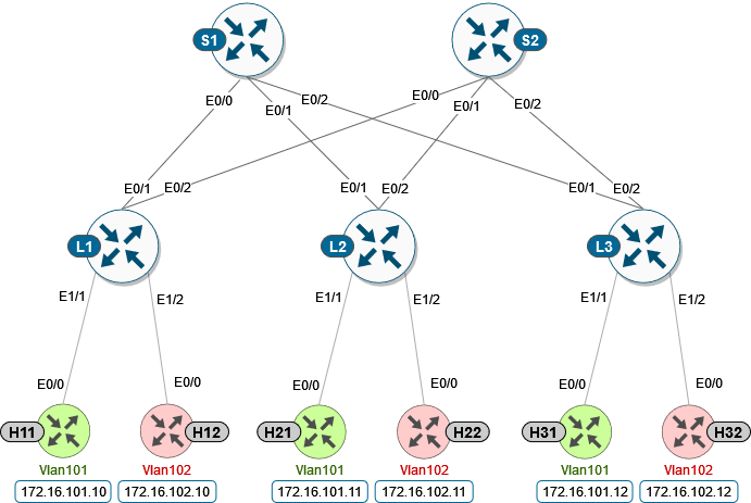
In this task, we will continue to work in previous spine / leaf topology and we will add L3 connectivity to fabric with addition of L3 VNI.
An EVPN VXLAN Layer 3 overlay network allows host devices in different Layer 2 networks to send Layer 3 or routed traffic to each other. The network forwards the routed traffic using a Layer 3 virtual network instance (VNI) and an IP VRF.
To get started, please select in lab manager option 02 to initialize lab devices.
Note
In this lab task, we will mainly focus on L3 part of the configuration. Therefore, L2 parts like L2 VNI /EVI / VNI, which we configured in previous task, are already preconfigured in this task and running.
Step 1: Create VRF
First step to configure L3 VNI routing is to have VRF defined with RD (route distinguisher) and import/export RTs (route targets) correctly configured.
Note
stitching is a new keyword added to the existing route-target configuration to specify the route targets to be used when doing EVPN related processing.
- EVPN->VRF
EVPN routes that contain RT matching an import “stitching RT” specified in a VRF configuration are accepted by the router and imported into the corresponding BGP L3VPN VRF. The resulting L3VPN prefix retains the same route target.
- VRF->EVPN
L3VPN routes that are imported into EVPN via “advertise l2vpn evpn” contain RTs specified by that VRF export “stitching RT”. Any original route targets are removed.
The existing RT configuration does not affect EVPN related processing, and you can have the same RT values for both base and VXLAN EVPN routes.
VRF name is green. RT 1:1 is to be used for base route target configuration and RT 10:10 for EVPN related processing.
L1/L2/L3 nodes
1 conf t
2 !
3 vrf def green
4  rd 1:1
5  address-family ipv4 unicast
6   route-target both 1:1
7   route-target both 10:10 stitching
You can check results with the show vrf detail <VRF_Name> command, e.g.:
L1 node
 1 cfg02-L1#show vrf detail green
 2 VRF green (VRF Id = 1); default RD 1:1; default VPNID <not set>
 3 New CLI format, supports multiple address-families
 4 Flags: 0x180C
 5 No interfaces
 6 Address family ipv4 unicast (Table ID = 0x1):
 7 Flags: 0x0
 8 Export VPN route-target communities
 9     RT:1:1
10 Import VPN route-target communities
11     RT:1:1
12 Export VPN route-target stitching communities
13     RT:10:10
14 Import VPN route-target stitching communities
15     RT:10:10
16 No import route-map
17 No global export route-map
18 No export route-map
Step 2: Configure MAC Aliasing for the distributed anycast gateway
Note
Distributed anycast gateway is a default gateway addressing mechanism in a BGP EVPN VXLAN fabric.
This feature enables the use of the same gateway IP address across all the Leafs in an EVPN VXLAN network, to ensure that every Leaf functions as the default gateway for the workloads directly connected to it. The feature facilitates flexible workload placement, host mobility, and optimal traffic forwarding across the BGP EVPN VXLAN fabric.
In our lab scenario we are using MAC aliasing, which allows the Leafs to advertise their VLAN MAC addresses as the gateway MAC addresses to all the other Leafs in the network. The Leafs in the network store the advertised MAC address as a gateway MAC address provided their VLAN IP address matches with the gateway IP address.
Alternative way (not shown in the lab scenarios) would be to manually configure the same MAC address on the VLAN interfaces of all Leaf switches in the network.
L1/L2/L3 nodes
1conf t
2!
3l2vpn evpn
4 default-gateway advertise
Verification output is part of the sh l2vpn evpn summary command:
 1cfg02-L1#show l2vpn evpn summary | include Default
 2Advertise Default Gateway: Yes
 3Default Gateway Addresses: 0
 4
 5cfg02-L2#show l2vpn evpn summary | include Default
 6Advertise Default Gateway: Yes
 7Default Gateway Addresses: 0
 8
 9cfg02-L3#show l2vpn evpn summary | include Default
10Advertise Default Gateway: Yes
11Default Gateway Addresses: 0
Step 3: Create VNI to vlan stitching for vlan901 (L3VNI), create SVIs for L2VNIs and L3VNI
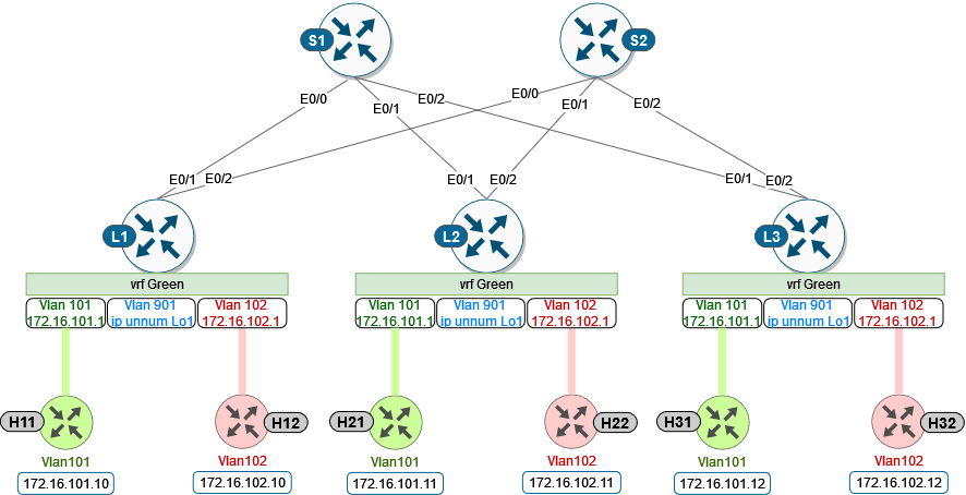
At this step, we create vlan 901 and SVI 901 to be mapped to L3VNI 50901. Similarly, we create SVIs for L2VNIs for routing between L2 domains.
All SVI interfaces are part of “green” VRF.
For L3VNI SVI make sure to enable IP processing on the Loopback1 interface without assigning an explicit IP address to the SVI.
VLAN |
VNI |
IP Address |
|---|---|---|
101 |
10101 |
172.16.101.1 |
102 |
10102 |
172.16.102.1 |
901 |
50901 |
ip unnumbered lo1 |
Note
Same gateway IP addresses are used for L2VNI SVI interfaces across all the Leafs, to make a distributed anycast gateway.
L1/L2/L3 nodes
 1conf t
 2!
 3vlan 901
 4!
 5vlan configuration 901
 6 member vni 50901
 7!
 8interface Vlan101
 9 vrf forwarding green
10 ip address 172.16.101.1 255.255.255.0
11 no shut
12!
13interface Vlan102
14 vrf forwarding green
15 ip address 172.16.102.1 255.255.255.0
16 no shut
17!
18interface vlan901
19 vrf forwarding green
20 ip unnumbered lo1
21 no autostate
22 no shut
Step 4: Configure BGP for VRF
For the VRF we need to advertise Layer 2 VPN EVPN routes within a tenant VRF, which can be done with advertise l2vpn evpn command under the corresponding BGP address-family on all Leafs.
L1/L2/L3 nodes
1conf t
2!
3router bgp 65001
4 address-family ipv4 unicast vrf green
5  advertise l2vpn evpn
Step 5: Add L3 SVI to NVE interface
Finally, on the NVE interface the L3VNI has to be associated with the VRF green, to indicate that it is being used for routing.
1conf t
2!
3interface nve1
4 member vni 50901 vrf green
Step 6: Verification
At this stage of the lab, we should be able to ping between the hosts located in different vlans since we enabled routing between different subnets via L3 VNI 50901 (Vlan901).
H11 node
 1cfg02-H11#ping 172.16.102.11
 2Type escape sequence to abort.
 3Sending 5, 100-byte ICMP Echos to 172.16.102.11, timeout is 2 seconds:
 4!!!!!
 5Success rate is 100 percent (5/5), round-trip min/avg/max = 1/1/2 ms
 6
 7cfg02-H11#ping 172.16.102.12
 8Type escape sequence to abort.
 9Sending 5, 100-byte ICMP Echos to 172.16.102.12, timeout is 2 seconds:
10!!!!!
11Success rate is 100 percent (5/5), round-trip min/avg/max = 1/1/1 ms
H12 node
 1cfg02-H12#ping 172.16.101.11
 2Type escape sequence to abort.
 3Sending 5, 100-byte ICMP Echos to 172.16.101.11, timeout is 2 seconds:
 4!!!!!
 5Success rate is 100 percent (5/5), round-trip min/avg/max = 1/1/2 ms
 6
 7cfg02-H12#ping 172.16.101.12
 8Type escape sequence to abort.
 9Sending 5, 100-byte ICMP Echos to 172.16.101.12, timeout is 2 seconds:
10!!!!!
11Success rate is 100 percent (5/5), round-trip min/avg/max = 1/1/1 ms
Let’s verify now a state of the control plane on our devices. As you can see below, NVE interface state is Up. In terms of EVI 101 and 102, we can see that state is established, which means that EVI was successfully provisioned on device. From the outputs, we can also verify L2 and L3 VNI information’s for corresponding EVI.
L1 node
 1cfg02-L1#show nve int nve1
 2Interface: nve1, State: Admin Up, Oper Up, Encapsulation: Vxlan,
 3BGP host reachability: Enable, VxLAN dport: 4789
 4VNI number: L3CP 1 L2CP 2 L2DP 0
 5source-interface: Loopback1 (primary:10.1.254.3 vrf:0)
 6tunnel interface: Tunnel0
 7
 8cfg02-L1#show l2vpn evpn evi 101 detail
 9EVPN instance:       101 (VLAN Based)
10RD:                10.1.255.3:101 (auto)
11Import-RTs:        65001:101
12Export-RTs:        65001:101
13Per-EVI Label:     none
14State:             Established
15Replication Type:  Ingress (global)
16Encapsulation:     vxlan
17IP Local Learn:    Enabled (global)
18Adv. Def. Gateway: Enabled (global)
19Re-originate RT5:  Disabled
20Adv. Multicast:    Disabled (global)
21Vlan:              101
22    Ethernet-Tag:    0
23    State:           Established
24    Flood Suppress:  Attached
25    Core If:         Vlan901
26    Access If:       Vlan101
27    NVE If:          nve1
28    RMAC:            aabb.cc80.0300
29    Core Vlan:       901
30    L2 VNI:          10101
31    L3 VNI:          50901
32    VTEP IP:         10.1.254.3
33    VRF:             green
34    IPv4 IRB:        Enabled
35    IPv6 IRB:        Disabled
36    Pseudoports:
37    Ethernet0/0 service instance 101
38        Routes: 0 MAC, 1 MAC/IP
39    Peers:
40    10.1.254.4
41        Routes: 2 MAC, 2 MAC/IP, 1 IMET, 0 EAD
42    10.1.254.5
43        Routes: 2 MAC, 2 MAC/IP, 1 IMET, 0 EAD
44
45cfg02-L1#show l2vpn evpn evi 102 detail
46EVPN instance:       102 (VLAN Based)
47RD:                10.1.255.3:102 (auto)
48Import-RTs:        65001:102
49Export-RTs:        65001:102
50Per-EVI Label:     none
51State:             Established
52Replication Type:  Static
53Encapsulation:     vxlan
54IP Local Learn:    Enabled (global)
55Adv. Def. Gateway: Enabled (global)
56Re-originate RT5:  Disabled
57Adv. Multicast:    Disabled (global)
58Vlan:              102
59    Ethernet-Tag:    0
60    State:           Established
61    Flood Suppress:  Attached
62    Core If:         Vlan901
63    Access If:       Vlan102
64    NVE If:          nve1
65    RMAC:            aabb.cc80.0300
66    Core Vlan:       901
67    L2 VNI:          10102
68    L3 VNI:          50901
69    VTEP IP:         10.1.254.3
70    MCAST IP:        225.0.1.102
71    VRF:             green
72    IPv4 IRB:        Enabled
73    IPv6 IRB:        Disabled
74    Pseudoports:
75    Ethernet0/0 service instance 102
76        Routes: 0 MAC, 1 MAC/IP
77    Peers:
78    10.1.254.4
79        Routes: 2 MAC, 2 MAC/IP, 0 IMET, 0 EAD
80    10.1.254.5
81        Routes: 2 MAC, 2 MAC/IP, 0 IMET, 0 EAD
We can also see that NVE peers has been discovered in both L2 and L3 VNI. Please note that type L3CP indicate that it is used for routing.
L1 node
 1cfg02-L1#show nve peers
 2'M' - MAC entry download flag  'A' - Adjacency download flag
 3'4' - IPv4 flag  '6' - IPv6 flag
 4
 5Interface  VNI      Type Peer-IP          RMAC/Num_RTs   eVNI     state flags UP time
 6nve1       50901    L3CP 10.1.254.4       aabb.cc80.0400 50901      UP  A/M/4 00:03:05
 7nve1       50901    L3CP 10.1.254.5       aabb.cc80.0500 50901      UP  A/M/4 00:02:56
 8nve1       10101    L2CP 10.1.254.4       5              10101      UP   N/A  00:04:24
 9nve1       10101    L2CP 10.1.254.5       5              10101      UP   N/A  00:04:19
10nve1       10102    L2CP 10.1.254.4       4              10102      UP   N/A  00:04:24
11nve1       10102    L2CP 10.1.254.5       4              10102      UP   N/A  00:04:19
In the routing table of VRF green, we should be able to see remote host routes learned from other Leafs over Vlan 901, e.g. L3 VNI vlan.
L1 node
 1cfg02-L1#show ip route vrf green
 2
 3Routing Table: green
 4
 5    172.16.0.0/16 is variably subnetted, 8 subnets, 2 masks
 6C        172.16.101.0/24 is directly connected, Vlan101
 7L        172.16.101.1/32 is directly connected, Vlan101
 8B        172.16.101.11/32 [200/0] via 10.1.254.4, 00:05:52, Vlan901
 9B        172.16.101.12/32 [200/0] via 10.1.254.5, 00:05:53, Vlan901
10C        172.16.102.0/24 is directly connected, Vlan102
11L        172.16.102.1/32 is directly connected, Vlan102
12B        172.16.102.11/32 [200/0] via 10.1.254.4, 00:05:52, Vlan901
13B        172.16.102.12/32 [200/0] via 10.1.254.5, 00:05:53, Vlan901