Task CFG01: Configure L2 EVPN connectivity with Spines

In this task, we will be configuring L2 connectivity in EVPN fabric. L2 connectivity will be extended across the leaf switches which will allow hosts connected to different leafs communicate with each other over L2 domain. To achieve this, we will configure L2 VNI and hosts will be able to communicate within same L2 domain only.
To get started, please select in lab manager option 01 to initialize lab devices.
Note
At beginning of this task, underlay configuration was already preconfigured for you. This includes configuration of IGP - OSPF for loopback reachability and multicast routing to support flooding of broadcast / multicast / unknown unicast (BUM) traffic.
Step 1: Configure L2VPN and VNI-EVI-VLAN stitching
We will start with L2VPN configuration. Configuration can be defined either in global context (l2vpn evpn) or per instance (l2vpn evpn instance …). In case that settings are not overridden in per instance context, they are inherited from global.
First, we will define replication type based on which we will be flooding BUM traffic in the fabric. The BGP EVPN control plane uses two methods for this purpose: multicast based (static), where multicast is flooded over dedicated multicast group to rest of the leaf switches or unicast based (ingress replication - ingress), where BUM traffic is delivered to leaf switches over unicast.
In this scenario, we will configure global context with replication type ingress (unicast based) and define two EVI instances – 101 and 102. Parameters of each EVI instance can be found in table below.
EVI |
VLAN |
VNI |
Replication |
|---|---|---|---|
101 |
101 |
10101 |
ingress (unicast) |
102 |
102 |
10102 |
static (multicast) |

Note
VXLAN encapsulation format is a default setting.
EVPN instance needs to be explicitly configured only when something needs to be configured per EVPN instance such as a route target, encapsulation or replication type.
L1/L2/L3 nodes
 1conf t
 2!
 3l2vpn evpn
 4 replication-type ingress
 5!
 6l2vpn evpn instance 101 vlan-based
 7 encapsulation vxlan
 8!
 9l2vpn evpn instance 102 vlan-based
10 encapsulation vxlan
11 replication-type static
12!
13vlan configuration 101
14 member evpn-instance 101 vni 10101
15vlan configuration 102
16 member evpn-instance 102 vni 10102
Step 2: Configure NVE interface
Next, we have to configure network virtualization endpoint (NVE) interface. The NVE interface is a logical interface where encapsulation and decapsulation of traffic happens for VXLAN traffic.
Specified replication type defined on NVE interface have to match replication type on EVI instance. In case of multicast based replication (static), we have to define multicast group which will be used for flooding of BUM traffic. In case of unicast based replication (ingress), this is not needed since BGP control plane will build the list of leafs where BUM traffic have to be replicated via unicast.
In this topology, we are using Loopback 0 for underlay routing and Loopback 1 as a source of VXLAN tunnel. Therefore, we will specify Loopback 1 as source for NVE interface. Loopback 1 should be seen as next-hop for EVPN routes.
L1/L2/L3 nodes
1conf t
2!
3interface nve1
4 no ip address
5 source-interface Loopback1
6 host-reachability protocol bgp
7 member vni 10101 ingress-replication
8 member vni 10102 mcast-group 225.0.1.102
Step 3: Configure BGP
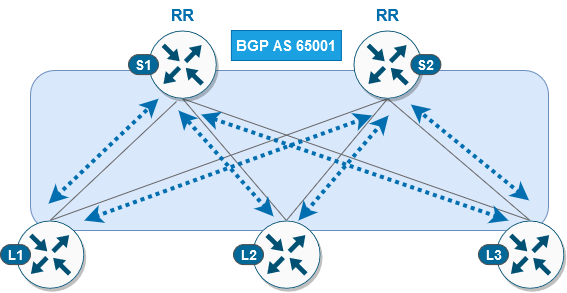
As last step, we will configure BGP protocol, so we can advertise host reachability information to the fabric via L2VPN EVPN address family. In this scenario, both spine and leaf switches are part of same AS 65001 and spine switches are acting like route reflectors.
L1/L2/L3 node
 1conf t
 2!
 3router bgp 65001
 4 bgp router-id interface Lo0
 5 no bgp default ipv4-unicast
 6 neighbor 10.1.255.1 remote-as 65001
 7 neighbor 10.1.255.1 update-source Loopback0
 8 neighbor 10.1.255.2 remote-as 65001
 9 neighbor 10.1.255.2 update-source Loopback0
10 !
11 address-family l2vpn evpn
12  neighbor 10.1.255.1 activate
13  neighbor 10.1.255.1 send-community both
14  neighbor 10.1.255.2 activate
15  neighbor 10.1.255.2 send-community both
S1/S2 node
 1conf t
 2!
 3router bgp 65001
 4 bgp router-id interface Lo0
 5 no bgp default ipv4-unicast
 6 neighbor 10.1.255.3 remote-as 65001
 7 neighbor 10.1.255.3 update-source Loopback0
 8 neighbor 10.1.255.4 remote-as 65001
 9 neighbor 10.1.255.4 update-source Loopback0
10 neighbor 10.1.255.5 remote-as 65001
11 neighbor 10.1.255.5 update-source Loopback0
12 !
13 address-family l2vpn evpn
14  neighbor 10.1.255.3 activate
15  neighbor 10.1.255.3 send-community both
16  neighbor 10.1.255.3 route-reflector-client
17  neighbor 10.1.255.4 activate
18  neighbor 10.1.255.4 send-community both
19  neighbor 10.1.255.4 route-reflector-client
20  neighbor 10.1.255.5 activate
21  neighbor 10.1.255.5 send-community both
22  neighbor 10.1.255.5 route-reflector-client
After completion of BGP configuration on both leaf and spine switches, we can verify status of BGP peering’s on spines. We should see that both spine switches have running BGP peering with all 3 leafs.
S1 node
1cfg01-S1#show bgp l2vpn evpn summary | beg Neighbor
2Neighbor        V           AS MsgRcvd MsgSent   TblVer  InQ OutQ Up/Down  State/PfxRcd
310.1.255.3      4        65001    2936    2954       16    0    0 1d20h           0
410.1.255.4      4        65001    2944    2950       16    0    0 1d20h           0
510.1.255.5      4        65001    2936    2947       16    0    0 1d20h           0
S2 node
1cfg01-S2#show bgp l2vpn evpn summary | beg Neighbor
2Neighbor        V           AS MsgRcvd MsgSent   TblVer  InQ OutQ Up/Down  State/PfxRcd
310.1.255.3      4        65001    2942    2951       16    0    0 1d20h           0
410.1.255.4      4        65001    2941    2942       16    0    0 1d20h           0
510.1.255.5      4        65001    2947    2952       16    0    0 1d20h           0
Step 4: Verification
At this stage of the lab, we should be able to ping between hosts located in same subnet over vlan 101 (subnet 172.16.101.0/24) and vlan 102 (subnet 172.16.102.0/24).
Note
It may take a few minutes for fabric to converge after the configuration changes above, before the connectivity between hosts can be established.
H11 node
 1cfg01-H11#ping 172.16.101.11
 2Type escape sequence to abort.
 3Sending 5, 100-byte ICMP Echos to 172.16.101.11, timeout is 2 seconds:
 4.!!!!
 5Success rate is 80 percent (4/5), round-trip min/avg/max = 1/1/1 ms
 6
 7cfg01-H11#ping 172.16.101.12
 8Type escape sequence to abort.
 9Sending 5, 100-byte ICMP Echos to 172.16.101.12, timeout is 2 seconds:
10.!!!!
11Success rate is 80 percent (4/5), round-trip min/avg/max = 1/1/2 ms
12cfg01-H11#
H12 node
 1cfg01-H12#ping 172.16.102.11
 2Type escape sequence to abort.
 3Sending 5, 100-byte ICMP Echos to 172.16.102.11, timeout is 2 seconds:
 4.!!!!
 5Success rate is 80 percent (4/5), round-trip min/avg/max = 1/1/1 ms
 6
 7cfg01-H12#ping 172.16.102.12
 8Type escape sequence to abort.
 9Sending 5, 100-byte ICMP Echos to 172.16.102.12, timeout is 2 seconds:
10.!!!!
11Success rate is 80 percent (4/5), round-trip min/avg/max = 1/1/2 ms
12cfg01-H12#
As you can see on both hosts, they were able to learn remote MAC address via ARP resolution since ARP request/reply was flooded either via unicast or multicast, depending on replication method, in fabric.
Note
In the outputs below, you can see that IP addresses 172.16.101.1 / 172.16.102.1 have incomplete ARP entry. These IP addresses are used as default gateways for their respective subnet. Purpose of this lab task is to demonstrate L2 connectivity, and these IP addresses will be added as part of next lab task, where we will be configuring L3 connectivity over fabric.
H11 node
1cfg01-H11#show ip arp
2Protocol  Address          Age (min)  Hardware Addr   Type   Interface
3Internet  172.16.101.1            0   Incomplete      ARPA
4Internet  172.16.101.10           -   0000.0001.0101  ARPA   Ethernet0/0
5Internet  172.16.101.11           0   0000.0002.0101  ARPA   Ethernet0/0
6Internet  172.16.101.12           0   0000.0003.0101  ARPA   Ethernet0/0
H12 node
1cfg01-H12#show ip arp
2Protocol  Address          Age (min)  Hardware Addr   Type   Interface
3Internet  172.16.102.1            0   Incomplete      ARPA
4Internet  172.16.102.10           -   0000.0001.0102  ARPA   Ethernet0/0
5Internet  172.16.102.11           0   0000.0002.0102  ARPA   Ethernet0/0
6Internet  172.16.102.12           0   0000.0003.0102  ARPA   Ethernet0/0
Let’s verify also control plane state on leaf switches. As you can see below, NVE peers been discovered over L2 VNI. Please note that type L2CP indicate that it is used for L2 connectivity.
L1 node
1cfg01-L1#show nve peers
2'M' - MAC entry download flag  'A' - Adjacency download flag
3'4' - IPv4 flag  '6' - IPv6 flag
4
5Interface  VNI      Type Peer-IP          RMAC/Num_RTs   eVNI     state flags UP time
6nve1       10101    L2CP 10.1.254.4       3              10101      UP   N/A  1d19h
7nve1       10101    L2CP 10.1.254.5       3              10101      UP   N/A  1d19h
8nve1       10102    L2CP 10.1.254.4       2              10102      UP   N/A  1d19h
9nve1       10102    L2CP 10.1.254.5       2              10102      UP   N/A  1d19h
Based on the available routes in BGP protocol, device will populate l2route table with locally originated routes (L2VPN flag) and remote learned routes (BGP flag). We can see also information about associated EVI instance and next hop information including VNI and remote peer IP address in case of remote entry.
L1 node
1cfg01-L1#show l2route evpn mac ip
2EVI       ETag  Prod    Mac Address         Host IP                Next Hop(s)
3----- ---------- ----- -------------- --------------- --------------------------
4101          0 L2VPN 0000.0001.0101   172.16.101.10                  Et1/1:101
5101          0   BGP 0000.0002.0101   172.16.101.11         V:10101 10.1.254.4
6101          0   BGP 0000.0003.0101   172.16.101.12         V:10101 10.1.254.5
7102          0 L2VPN 0000.0001.0102   172.16.102.10                  Et1/2:102
8102          0   BGP 0000.0002.0102   172.16.102.11         V:10102 10.1.254.4
9102          0   BGP 0000.0003.0102   172.16.102.12         V:10102 10.1.254.5